Week 16: Machine Design
The ongoing group assignment
- actuate and automate your machine
- document the group project and your individual contribution
Structure of the documentation
On this page I wil first describe my contribution to the team work. This I will do chronologically, describing what I did every day. After that I will show that I understand the code we used. I will end with learning outcomes.
Friday may 11th
The day started at 10 with a 90 minutes lecture of Emma on the actuation of motors. Very usefull. Also we where very happy to hear we could use Arduino boards and motor drivers for the actuation. After that I spend some hours(!) on making extra slots for the switches. As this is work that belongs to week 15, I descibe it there.
My task was to look for a piece of code that make the motor of the X-arm stop when it reaches the end or the 0-point of the arm. I looked at the Arduino references page and found the while control structure. It lets you perform something under certain conditions. It is a boolean operation. I our case I wrote while(digitalRead(Switch1Pin) == HIGH) With that you also need to set a pin that reads the state of the switch. I wrote #define SWITCH1Pin 11. Henk told me we had to use pin 11, but later he found out it should be A4. We connected the Switch so that it would have a HIGH state if not pressed and got this code to work:
#define EN        8      //Negative Enable pin
#define X_DIR     5      //Direction pin
#define X_STP     2     //Step pin

#define SWITCH1Pin  A5  //A5 is the pin of the first switch
#define SWITCH2Pin  A4  //A5 is the pin of the second switch

int delayTime=80; //Delay between each pause (uS)
int stps=200;// Steps to move microsteps 1/32 (200*32 = 6400)
void step(boolean dir, byte dirPin, byte stepperPin, int steps) {

  digitalWrite(dirPin, dir); //

  for (int i = 0; i < steps; i++) {
    digitalWrite(stepperPin, HIGH);
    delayMicroseconds(delayTime);
    digitalWrite(stepperPin, LOW);
    delayMicroseconds(delayTime);
  }
}
void setup(){
  pinMode(X_DIR, OUTPUT); //direction pin = output
  pinMode(X_STP, OUTPUT); //step pin = output
  pinMode(EN, OUTPUT); //negative enable pin  =output
  digitalWrite(EN, LOW); //start negative enable pin at low
  pinMode(SWITCH1Pin, INPUT_PULLUP); //Set switch to input pullup
  pinMode(SWITCH2Pin, INPUT_PULLUP); //Set switch to input pullup
}
void loop(){

// from 0-36

//  int switch1 = (digitalRead(Switch1Pin);
// false 0-36
//true 36-0

int SW1State = digitalRead(SWITCH1Pin); //read the switch and make it a 'state'
int SW2State = digitalRead(SWITCH2Pin); //read the switch and make it a 'state'

if (SW1State == LOW && SW2State == LOW) //If the states of both the switches are low
  {
  for(int i =0; i<10; ++i){
      step(false, X_DIR, X_STP, stps); //true equals back towards motor

  }
 }
}
With this code the motor turned until we pressed one of the switches. So that was succesfull. Unfortunately we didn't film this, what a shame!
The next week we decided to not implement the security switches. We figured that with the code we where writing that makes the 'sandwich-arm' go to a location and back to 0 again, we didn't need a switch to prevent the arm from bumping the stage. I guess we didn't give it much thought. Emma pointed out later that in case of power failure and the machine would start as soon power is regained, the 0-state is lost and the arm would actually very likely bump into the stage. That is true off course and on a second version of the machine we would definitely build them in.
Monday 14th of May
Me, Johanna and Henk started off at 13.00 by describing in words what the void loop code should do. We figured that it should be something like this:
- Do nothing until button is pressed
- When button is pressed, generate a random number: 0, 1, 2 or 3
- When number is x, execute loop x
- Loop x =
- Sandwich motor move to station x+1
- Delay until the topping is dropped
- Topping motor x+1 delay until Sandwich has arrived
- Topping motor x+1 open
- Topping motor x+1 delay
- Topping motor x+1 close
- Sandwich motor go back to position 0
This would mean we need 1 loop for the generation of the random number and then 4 loops for each topping station. This also meant that we didn't actually need the end switches, as the program counts the steps to be taken and then returns to the first position. Emma pointed out that in the case you loose power in the middle of an excecution and the stage is half way the X-axis, and then power comes back, Arduino starts from the point the stage is in at that point with potentially the motor bumping in the end of the X-axis. For a final product that will be a serious problem.
I found a piece of Arduino IDE code that generates a random number here. It looks like this:
long randNumber;

void setup(){
  Serial.begin(9600);

  // if analog input pin 0 is unconnected, random analog
  // noise will cause the call to randomSeed() to generate
  // different seed numbers each time the sketch runs.
  // randomSeed() will then shuffle the random function.
  randomSeed(analogRead(0));
}

void loop() {
  // print a random number from 0 to 299
  randNumber = random(300);
  Serial.println(randNumber);

  // print a random number from 10 to 19
  randNumber = random(10, 20);
  Serial.println(randNumber);

  delay(50);
}randNumber = random(0, 4);
I also looked for a piece of code that enables you to call on another loop. I found this conversation informative. So Henk implemented it in the code like this:
 void loop(){

  randoM();

if (randNumber == 0){
  stage1();
//0= position 1

}
if (randNumber == 1){
  stage2();
//8= position 2

}
if (randNumber == 2){
  stage3();
//23=position 3

}
if (randNumber == 3){
  stage4();
//33=position 4

}
}
				void stage1(){
//position 1. Don't move the stage), use motor connected to the Z-dir to release some topping, wait some ms.
      step(false, Z_DIR, Z_STP, 1600); //Z, Clockwise
 delay(2000);
}
The number you see for the positions like this //33=position 4 are the result of counting the steps until the stage reached one of the stations. We uploaded this code
for(int i =0; i<1; ++i){
      step(true, Y_DIR, Y_STP, stps); //true equals back towards motor
 delay(500);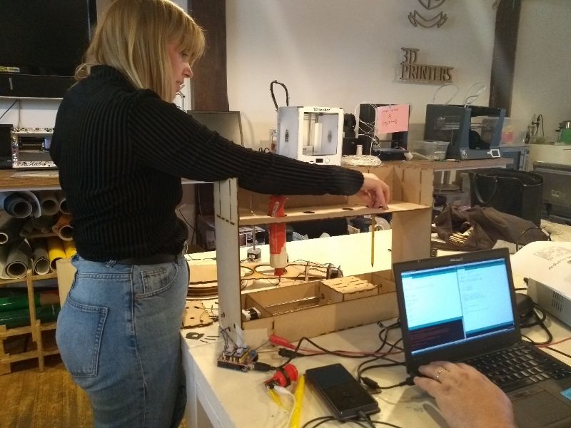
May 15th
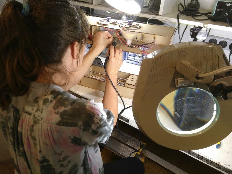
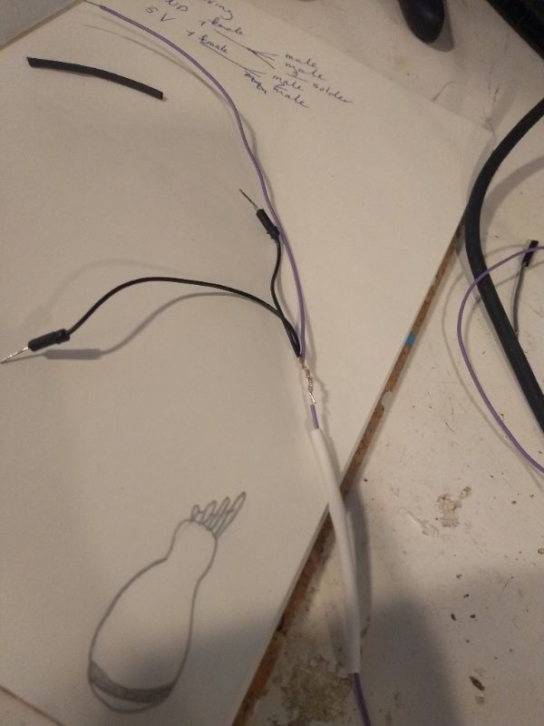 Today I could only be in for an hour. I made the wires for the stepper motors. We needed a wire that connected both topping motors and the button to 1 GND pin on the Arduino. And we needed a wire that connected both the topping motors to one VCC (5V) pin of the Arduino. I used a wire cutter, a wire stripper and a heat shrink tube to make them
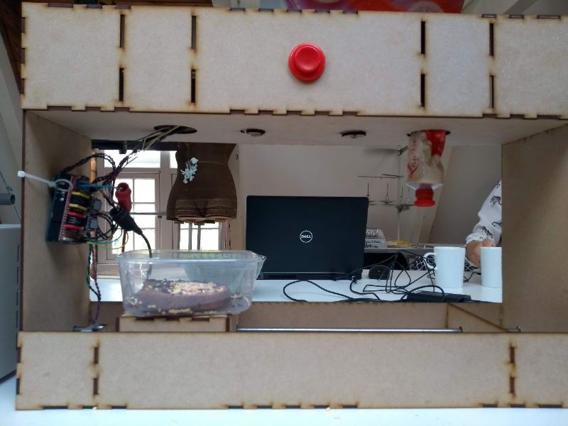
Wednesday May 16th
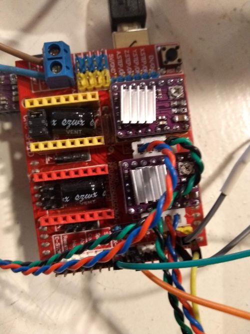
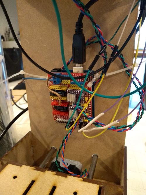
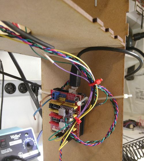
Today I re-wired the Arduino to the inside of the machine. First I took a picture of how everything was connected. Then I used tie wraps to attach the Arduino to the machine and some more tie wraps to hold the wires. Later Henk also put a duct tape. Emma really wasn't happy with the wiring, so I improved my work on this. I soldered the wires to the red button instead of using alligator clips. I made some of the wires shorter and led them to the hole in the middle panel.
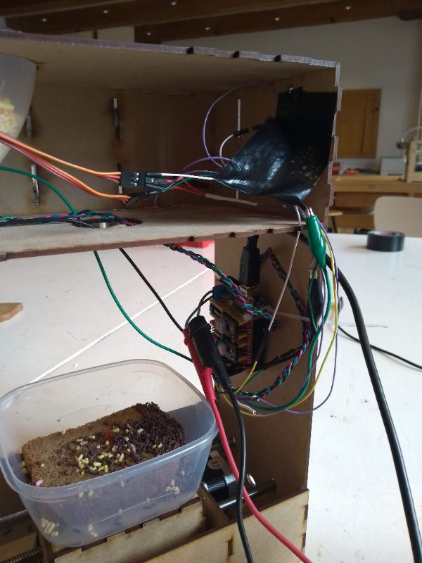
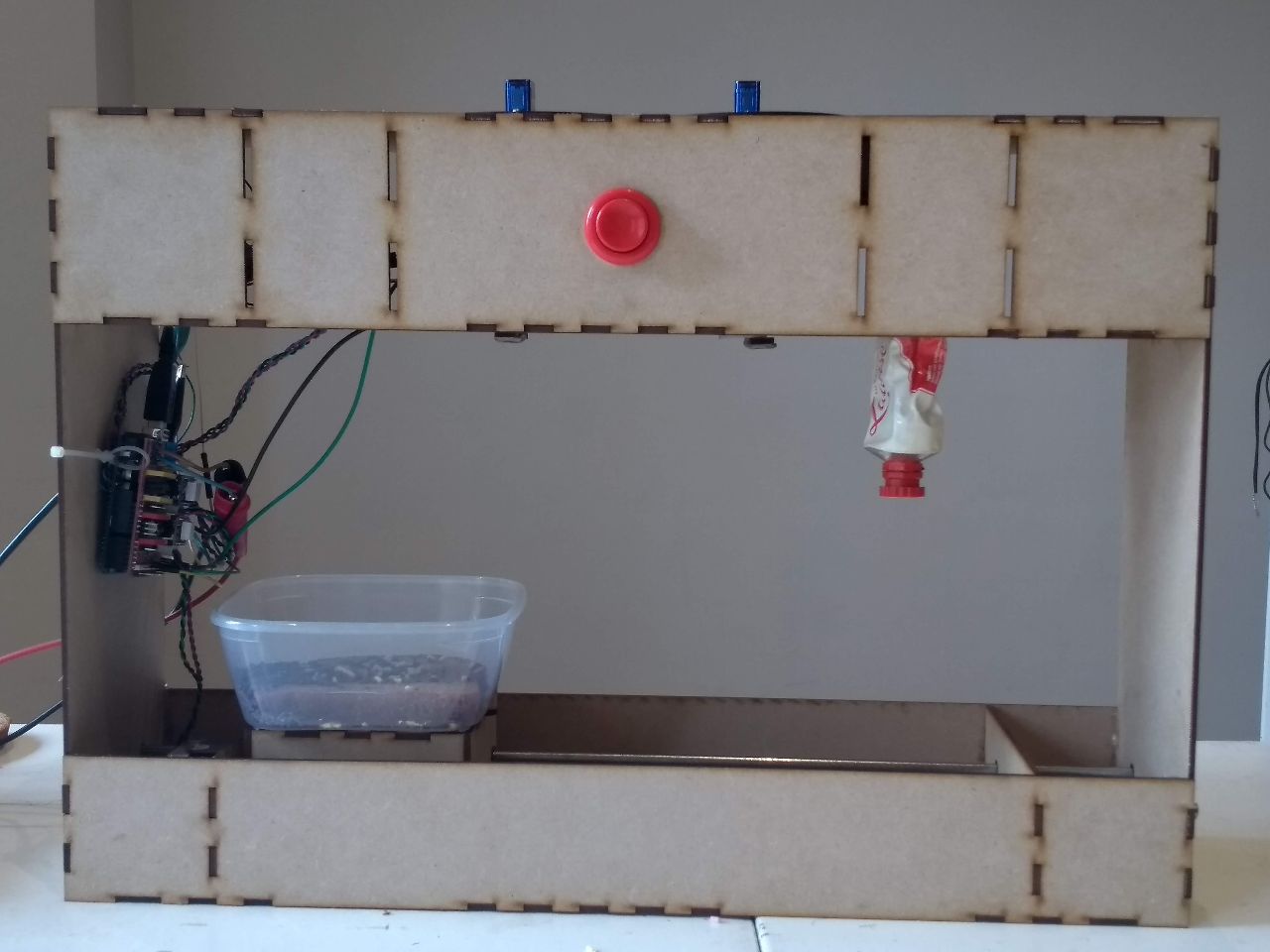
When the wiring was done, we could also really assemble the machine. We had some trouble with fitting in the big motor for the ketchup tube. The housing was a bit to big. In the end we decided to not put on the back panel and to use duct tape to keep the upper and the middle panel in such a distance that the funnels would fit it without the openers falling out every time the topping motors turned.
And finally it is there: The Random Dutch Lunch Generator!!
Understanding the code
I have been thinking along with Henk and Johanna to get the code right. Here I explain what it does.
// Include servo library for the fusels
// see https://www.arduino.cc/en/Reference/Servo
#include Servo.h>

Servo myservo1;  // create servo object to control a servo
Servo myservo2;  // create servo object to control a servo

// for using random numbers see
// https://www.arduino.cc/reference/en/language/functions/random-numbers/randomseed/

long randNumber; // long is the variable that is supposed to hold the random number

#define EN        8  // This is the pin to enable the NEMA 17 stepper motors

//Direction pins of the stepper motors. true is towards the motor, false is away from the motor
#define X_DIR     5  // for tube 2. We eventually didn't use it anymore
#define Y_DIR     6  //for the stage
#define Z_DIR     7  // for tube 1

//These pins make the stepper motors turn the given amount of steps. Again eventually we only used two of them.
#define X_STP     2
#define Y_STP     3
#define Z_STP     4

#define SWITCH1Pin  A5 //This is the pin for the random generation switch

//DRV8825.
int delayTime=60; //Delay between each pause (uS)
int stps=6400;// Steps to move microsteps 1/32 (200*32 = 6400)
int pos = 180;    // variable to store the servo position. It needs to turn 180 out of 360 every time

void step(boolean dir, byte dirPin, byte stepperPin, int steps) // The void step code we got from Emma.
// I guess it states what a step is in terms of high and low on a pin

{

  digitalWrite(dirPin, dir);

  for (int i = 0; i < steps; i++) {

    digitalWrite(stepperPin, HIGH);

    delayMicroseconds(delayTime);

    digitalWrite(stepperPin, LOW);

    delayMicroseconds(delayTime);

  }

}

void setup(){

    Serial.begin(9600);
    randomSeed(analogRead(0));
  // if analog input pin 0 is unconnected, random analog
  // noise will cause the call to randomSeed() to generate
  // different seed numbers each time the sketch runs.
  // randomSeed() will then shuffle the random function.

  pinMode(Y_DIR, OUTPUT); pinMode(Y_STP, OUTPUT); // Stating that the corresponding pins are output for Motor for Stage

  pinMode(Z_DIR, OUTPUT); pinMode(Z_STP, OUTPUT); // Stating that the corresponding pins are output for Motor for tube 1

  pinMode(X_DIR, OUTPUT); pinMode(X_STP, OUTPUT); // Stating that the corresponding pins are output for Motor for tube 2. We eventualy did not use it

  pinMode(EN, OUTPUT); //Stating that the corresponding pin is output

  digitalWrite(EN, LOW); // The enable is negative, so LOW means it is ON

  pinMode(SWITCH1Pin, INPUT_PULLUP); //enable an internal pullup resistor for the switch

  // servo part in the setup
  myservo1.attach(9);  // attaches the servo on pin 9 to the servo object
  myservo2.attach(10);  // attaches the servo on pin 10 to the servo object

  for (pos = 0; pos <= 90; pos += 1) { // I think this should be 180 instead of 90
    myservo1.write(pos);
    myservo2.write(pos);
  }
}

void loop(){

int currentButtonState = digitalRead(SWITCH1Pin); //do nothing until the button is pressed
if (currentButtonState == LOW)  { //if the button is pressed
  randoM(); //generate a random number (The min and max are given in the void random loop)

if (randNumber == 0){ //if the random number is 0
  stage1(); //perform loop 1


}
if (randNumber == 1){ //if the random number is 1
  stage2(); //perform loop 2


}
if (randNumber == 2){ //if the random number is 2
  stage3(); //perform loop 3


}
if (randNumber == 3){ //if the random number is 3
  stage4(); //perform loop 4


    }
  }
}

void randoM(){ //the loop for generating a random number; 0,1,2 or 3
 randNumber = random(1, 4);
 Serial.println(randNumber); //if you define a pin for this, you can check the output on a serial monitor

}

void stage1(){
//position 1. Don't move the stage, here we have no topping
      step(false, Z_DIR, Z_STP, 1600); //Z, Clockwise
 delay(2000);
}

void stage2(){
//position 2. Move the stage 8 steps, release topping 2 (turn servo), wait some ms and return home.
// false 0-34 steps away from motor
//true 34-0 steps towards motor

  for(int i =0; i<8; ++i){
      step(false, Y_DIR, Y_STP, stps);
  }

  delay(2000);

  for (pos = 0; pos <= 90; pos += 1) { // goes from 0 degrees to 180 degrees, therefor it should say 180 here?
    // in steps of 1 degree
    myservo1.write(pos);              // tell servo to go to position in variable 'pos'
    delay(5);                       // waits 5ms for the servo to reach the position
  }

  delay(2000);

  for (pos = 90; pos >= 0; pos -= 1) { // goes from 180 degrees to 0 degrees
    myservo1.write(pos);              // tell servo to go to position in variable 'pos'
    delay(5);                       // waits 5ms for the servo to reach the position
  }

  delay(2000);

  for(int i =0; i<8; ++i){
      step(true, Y_DIR, Y_STP, stps); //true equals back towards
  }

  delay(2000);

}

void stage3(){
//position 3. Move the stage 23 steps, release topping 3 (turn servo), wait some ms and return home.


  for(int i =0; i<23; ++i){
      step(false, Y_DIR, Y_STP, stps); //true equals back from motor
  }

  delay(2000);

  for (pos = 0; pos <= 180; pos += 1) { // goes from 0 degrees to 180 degrees, in steps of 1 degree
    myservo2.write(pos);              // tell servo to go to position in variable 'pos'
    delay(5);                       // waits 5ms between each degree for the servo to reach the position (speed of the shaft)
  }

  delay(2000);

  for (pos = 180; pos >= 0; pos -= 1) { // goes from 180 degrees to 0 degrees
    myservo2.write(pos);              // tell servo to go to position in variable 'pos'
    delay(5);                       // waits 5ms between each degree for the servo to reach the position (speed of the shaft)
  }

 delay(2000);

  for(int i =0; i<23; ++i){
      step(true, Y_DIR, Y_STP, stps); //true equals back towards motor
  }


 delay(2000);
}

void stage4(){

  for(int i =0; i<33; ++i){
      step(false, Y_DIR, Y_STP, stps); //true equals back towards motor
  }

 delay(2000);

//turn motor tube 2

  step(false, X_DIR, X_STP, 3200); //Z, Clockwise

 delay(2000);

   for(int i =0; i<33; ++i){
      step(true, Y_DIR, Y_STP, stps); //true equals back towards motor
   }

  delay(2000);
}Learning outcomes and conclusions
- Making a machine with four people is complicated for two major reasons:
- The goal of learning tends to be overruled by the goal of making it work;
- Many steps of the proces are dependent on another wich makes dividing the tasks difficult.
- We should have thought of a housing of the wires.
- We should have looked for a suitable motor for the second tube earlier.
- We should have tested the mechanics more thoroughly before doing the actuation.
- A better version of the machine should have the switches to prevent it from bumpping into the stage.
- A better version of the machine would not spil toppings when the sandwich is not under it. The automation of the funnels was fine, but mechanically it didn't work well. A little research on funnel opening and closing should help. Maybe 3D-print a special funnel-opener.
- A better version of the machine would have an interface that could make you choose the toppings of your liking or make you choose for a random topping.
- We should have looked for tubes with peanut butter and apple sirop. Even Dutch people don't mix chocolate sprinkles with ketchup.